
Ankle Joints
The Ankle Joints differ from all the others as they use Linear Actuators.

The leg is made out of a 20 mm aluminium tube.
Swivel bearings are fitted into a 3D printed support and linked through CNC machined aluminium plates with a collar. The collar can be tightened to the leg tube with a tangent screw.
The linear actuators housings are inserted into the swivel bearings. 3D printed collars are glued on the opposite side to stop axially the linear actuators.

The Ankle is articulated with a cardan joint located at the lower end of the leg tube.
The axial movement coming from the Linear Actuator is transmitted to two Load Cells through small swivel joints and machined nuts. The Load Cells are then fastened to a CNC machined aluminium support.
Position Sensors Shafts are used as axis of the cardan joint. The shafts meet at the Cardan Cross Block which is machined from aluminium.
The y5 position sensor is mounted on a CNC machined 3 mm aluminium plate and its shaft is guided with a flanged ball bearing. Another CNC machined 3mm aluminium plate is also equiped with a similar ball bearing at the opposite side of the Cross Block.
Both plates are fastened together, along with a 3D printed block, to the leg tube with four M4 bolts.
The y5 Position Sensor Shaft crosses the Cardan Cross Block, 2 small ring spacers, and is blocked with a stop screw.

The x6 position sensor is mounted onto 6mm CNC machined aluminium Blocks. These Blocks will then be mounted on the robot foot. In this case, the Sensor Shaft is cut in two parts as it cannot cross the cardan block center (already occupied by x5 Sensor Shaft). Both are clamped to this block by four M3 screws.

The Load Cells support is fixed on the foot with the Ankle Assembly.

Then, the actuators are fitted onto the leg tube and the ankle swivel joints.

Position Sensors measure directly the angular position on y5 and x6 Ankle axis. However, Torques must be calculated from the Forces on the Load Cells (See Joints Control System Section).
Feet
Feet are made out of hand cut 4mm Carbon Epoxy Plates. Aluminium contact pads are located at each corner and are fastened with 3D printed spacers, washers and M4 domed head screws.
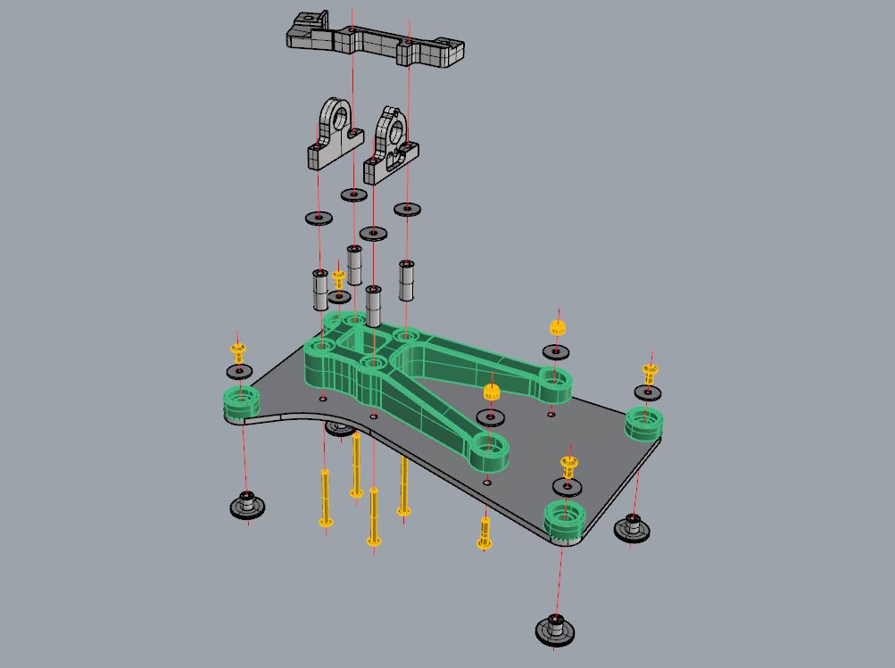
A 3D printed support is positionned between the Foot Plate and the Ankle Assembly. Four inserts are glued into this support in order to increase its strength and avoid crushing when tightening screws.
Four domed head screws cross the foot plate and the support and are tightened on tapped M4 holes on the 6 mm CNC machined blocks one one side, and on the load cells support on the other side.
So far, no sensor has been added on the feet to detect contact/force on the pads. The Robot Control relies only upon Ankle torques information.

And now a photo of the Ankle / Feet Assembly :

