The Pelvis connects left and right legs by mean of two CNC machined 2mm aluminium plates secured on upper and lower side of the z1 worm gears actuators.
Each actuator is held by three bolts. Washers are inserted between the plates and actuator housings to allow the planetary gearset reducer to fit between the two plates.
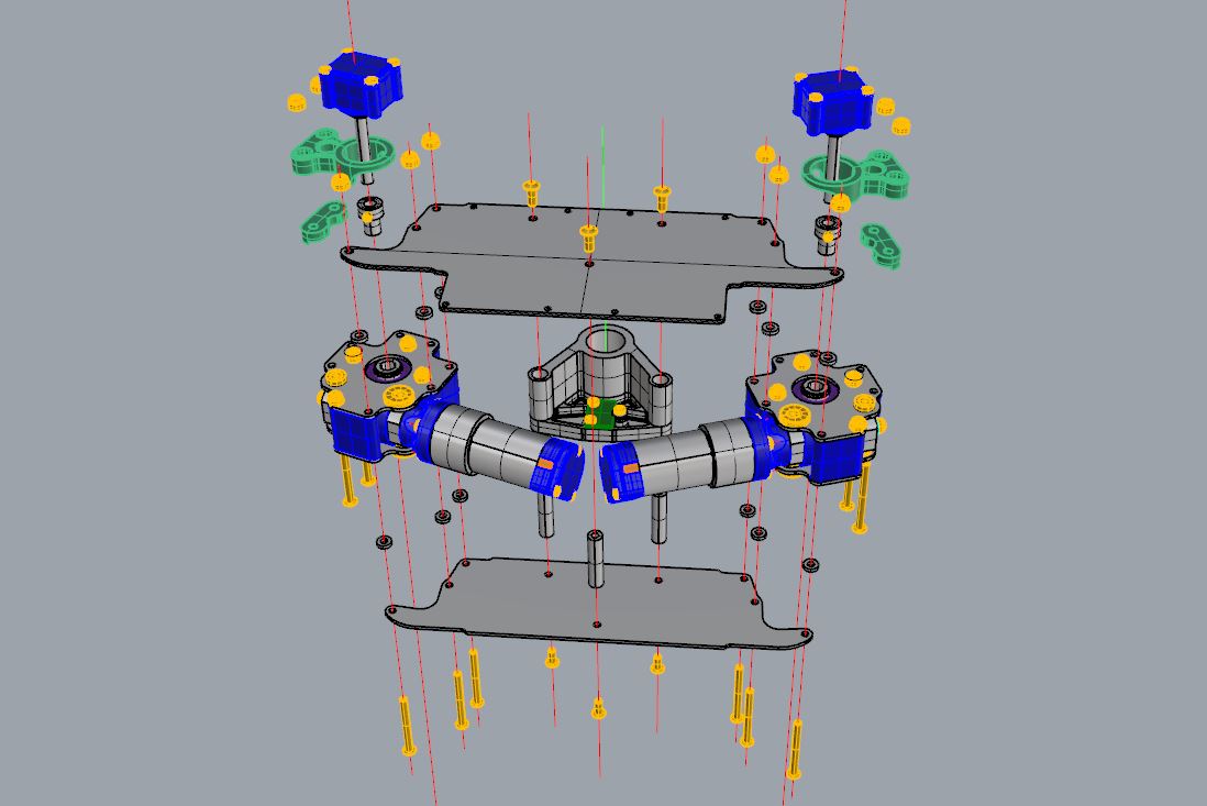
3 aluminium pilars/spacers are also fastened between upper and lower plates to increase pelvis stiffness. The two rear pilars hold a 3D printed structure with a large bore dedicated to receive the base of the “spinal chord” of the robot upper body.

This 3D printed structure also holds the IMU board. I use a IMU board based upon a InvenSense MPU6050 chip, communicating with I2C protocol.

View of the left lower side of the Pelvis. The right actuator has not yet been assembled. Note the “last minute” notches filed near the encoder case: My CAD model was not accurate regarding the angular position of the motor copper outputs / encoder case and mounting studs on the Flange. Minor issue..

View of the Pelvis on the operational robot. Note the control boards of the z1 axis in their blue 3D printed support. The Load Cells inputs are free (4 pins on the left side of the board) as these axis do not have Force Feedback (only position control).

