Bevel Gears Actuator description
The shaft is turned from Aluminium alloy (7075) and carries a 45 teeth gear held by four M3 countersunk head screws. The shaft is guided by ball bearings.
The ball bearings are inserted into 2 3D printed half shells.
Two CNC machined 2mm aluminium plates on each side of the shells close the actuator assembly. These plates are in contact with the ball bearings outer rings.

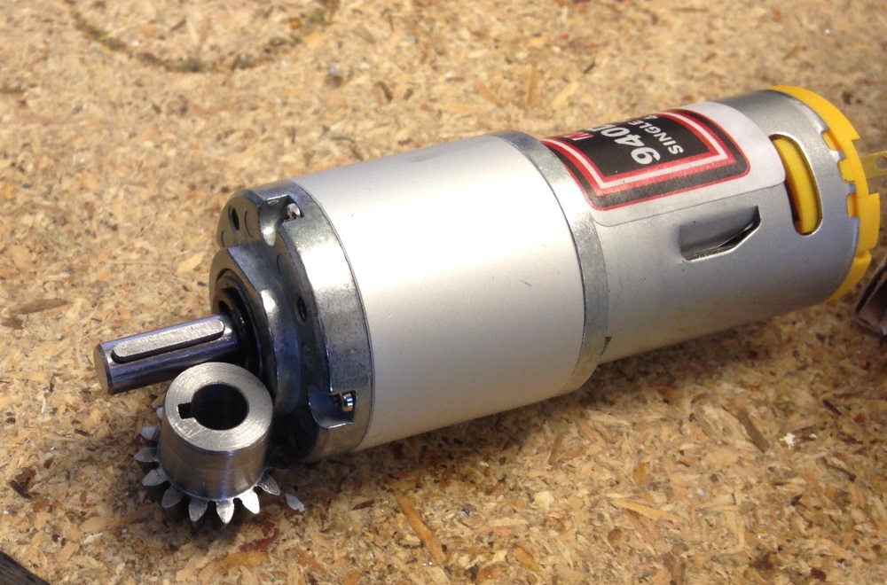
The 15 teeth bevel pinion drive uses a DC motor with a 1:100 planetary gearset reducer.
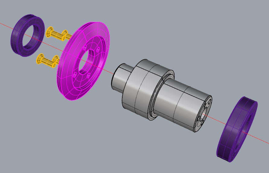
A key slot is machined into the output shaft of the reducer. the bevel pinion is mounted with a ball bearing and a 3D printed spacer is glued in order to prevent the bearing from sliding along the pinion outside diameter.
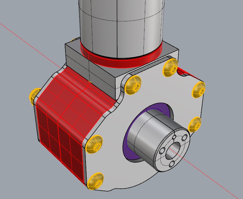
An aluminium support is mounted on the reducer housing with four M3 countersunk screws. The bevel pinion bearing is centered into the bore machined into the support.
A 3D printed spacer is inserted between the support and the reducer housing. Its thickness is adjusted in order to set/minimize gear backlash.

The bevel pinion drive assembly is then assembled with the bevel crown casing with four M4 domed head screws.
Close view of machined bevel gears. Note the key slot on the pinion.
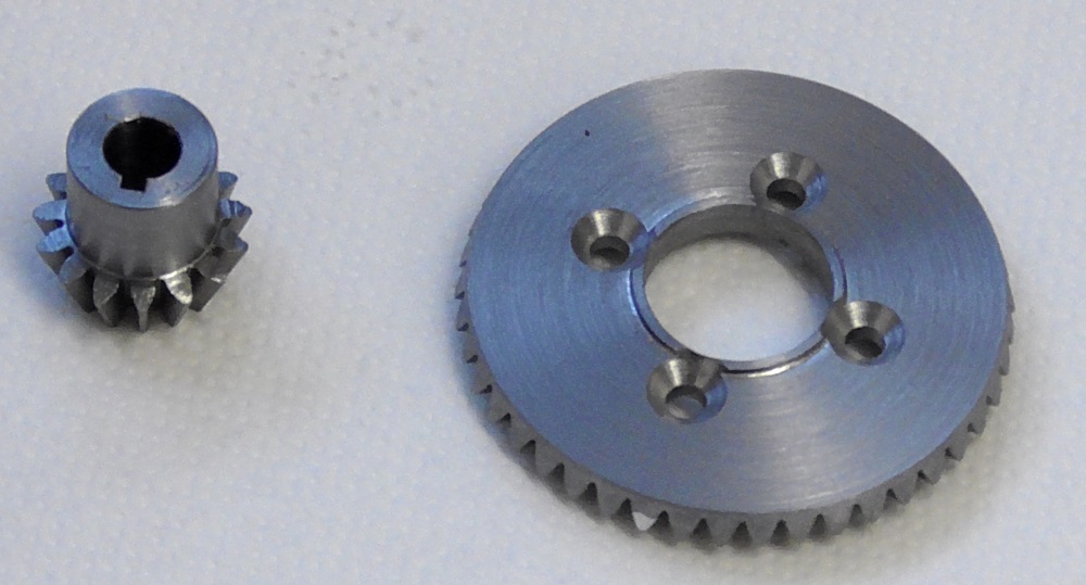
The pinion and motor output shaft with its key.
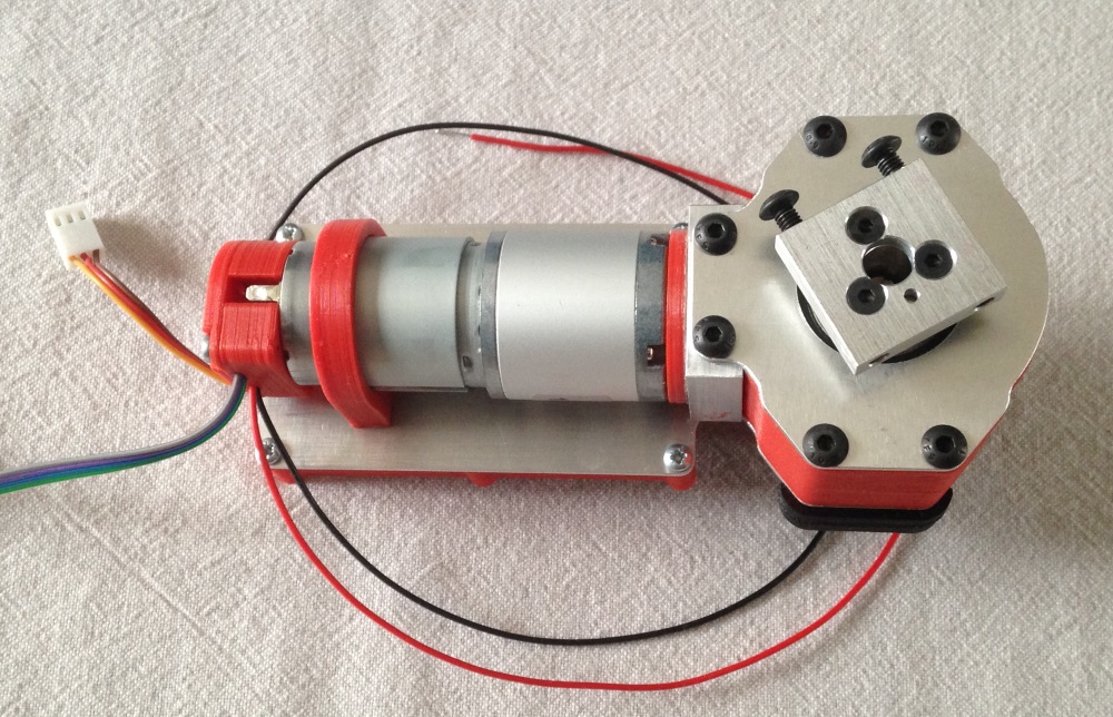
The complete Bevel Gear actuator: note the block fitted to the output shaft that allows connection to the next actuator of the robot.
The plate under the motor holds the Joint Control Board of the actuator.