I Designed 2 types of Joints Control Boards (JCB) :
- Single JCB used for joints z1, x2, y3 and y4
- Dual JCB used for joints y5 ans x6
JCBs communicate to the Robot Control Unit (RCU) with I2C ports set at 400 kHz
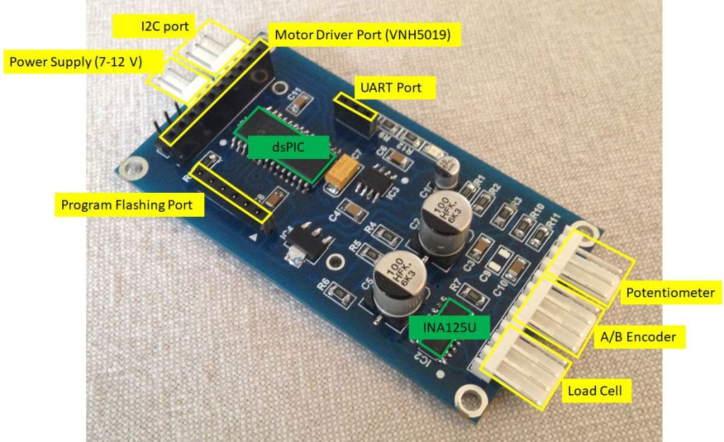
JCBs are built around a 16 bits microcontroller dsPIC33FJ128MC802 and integrate the following features :
- I2c Port (3 pins)
- dsPIC Flash programming port (6 pins)
- UART Port (3 pins) – Used only for debugging
- Load Cell port (4 pins)
- A/B encoder Port (4 pins)
- Potentiometer Port (3 pins)
- Motor Driver Port (10 pins)
The Motor Driver is a ST VNH5019 H-Bridge (12A, 5.5 – 24V ) board from Pololu (RB-Pol-173).
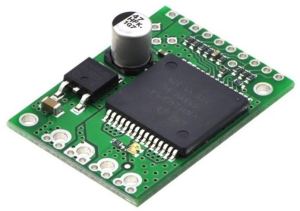
With 12 A current capacity, it is oversized but I wanted something robust ! By the way I never broke any of these boards so far during my many experiments and mistakes… It can work efficiently with 20 kHz PWM which is very convenient, as no high pitch switching frequency can be heard. Imagine how long testing / tuning sequences would be with 12 motors driven by 10 kHz or below PWM !
dsPIC33FJ128MC802 have built-in PWM outputs than can be easily programmed.
A/B Encoder
dsPIC33FJ128MC802 has two built-in A/B encoder inputs. The Pololu A/B encoders can be connected directly to the µController.

Load Cells
Load Cell signal is amplified by a specialised IC, the INA125U from Texas Instruments. The amplified signal is then directed to a dsPIC built-in 12 bits ADC input.
Potentiometer
The potentiometer is connected to another dsPIC 12 bits ADC input. I added a crude Low Pass filter in order to minimize high frequency noise on the potentiometer input.
Power Supplies
Power supply can either come from the Motor Driver Board if voltage does not exceed 12V or through a separate 7-12V.
5V and 3.3V are generated by linear voltage regulators routed on the JCBs. Leds have been added to check that both voltages are ON.
A jumper allows to select either power supplies.
As I use 24V motors, I applied a separate 8V power supply for the JCBs. I can therefore switch on separately Logic and Power of the actuators. I designed an interface board in order to manage the start sequence of the Robot, to communicate with the Control Pad and with the mini PC (see Interface Boards Section).
Single JCB
I Designed the board with DesignSpark (available for free at Radiospares). I built a first prototype by etching my own PCB then, when ultimate checks and modifications were OK, I ordered to a PCB manufacturer. It is fairly cheap to supply professional quality PCBs from specialized manufacturers in China (I paid about 40€ for 15 PCBs including shipping cost).
Photo of the Prototype board :
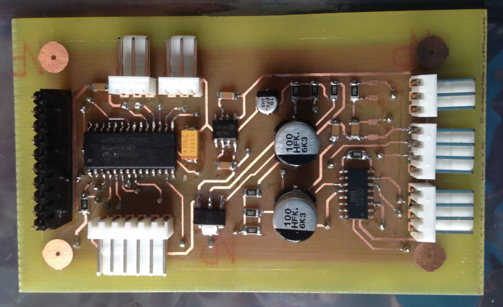
Photo of the final board. I had to manufacture 8 of these :
I soldered all the components and I felt quite happy with the result as this was my first experience with Surface Mount components: patience and flux !
Single JCB schematics can be downloaded here
Would you be interested in PCB routing files please contact me.
Dual JCB
I needed a dual JCB as I have to control simultaneously the ankle linear actuators. Two single boards would not have worked as control algorithm request both y5 and x6 position / torque information to control the motors.
The dsPIC33FJ128MC802 has enough I/O and calculation speed to deal with 2 joints at the same time. The Dual JCB integrates the following features (in red difference with Single JCB):
- I2c Port (3 pins)
- dsPIC Flash programming port (6 pins)
- UART Port (3 pins) – Used only for debugging
- 2 x Load Cell port (4 pins)
- 2 x A/B encoder Port (4 pins)
- 2 x Potentiometer Port (3 pins)
- 1 Motor Driver Port (13 pins)
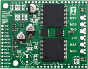
Pololu manufactures a dual VNH5019 board (RB-Pol-263)
.
The Dual JCB was designed and routed also with DesignSpark. PCBs were also ordered to the same PCB manufacturer. I had to manufacture two boards.

Dual JCB schematics can be downloaded here
Would you be interested in PCB routing files please contact me.
Photo of the JCB at the rear of the thighs complete with motor controllers. Single JCBs on the upper side into the red supports (x2 axis) and the two Dual JCBs on the lower side (y5 and x6).

