The hip has 3 rotary actuators. All 3 joints axis cross the same point in order to build a true controlled swivel joint.
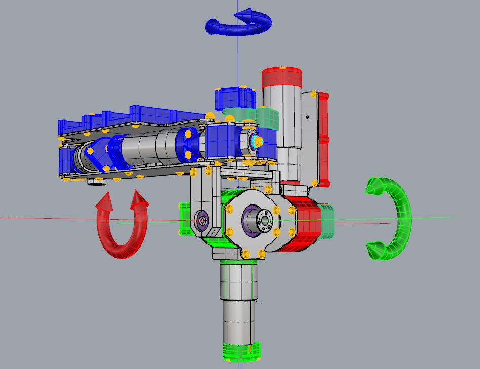
The first axis (blue) is z1, the second axis is x2 (red) and then the third axis is y3 (green).
z1 axis uses a worm gear actuator when both x2 and y3 use bevel gear actuators.

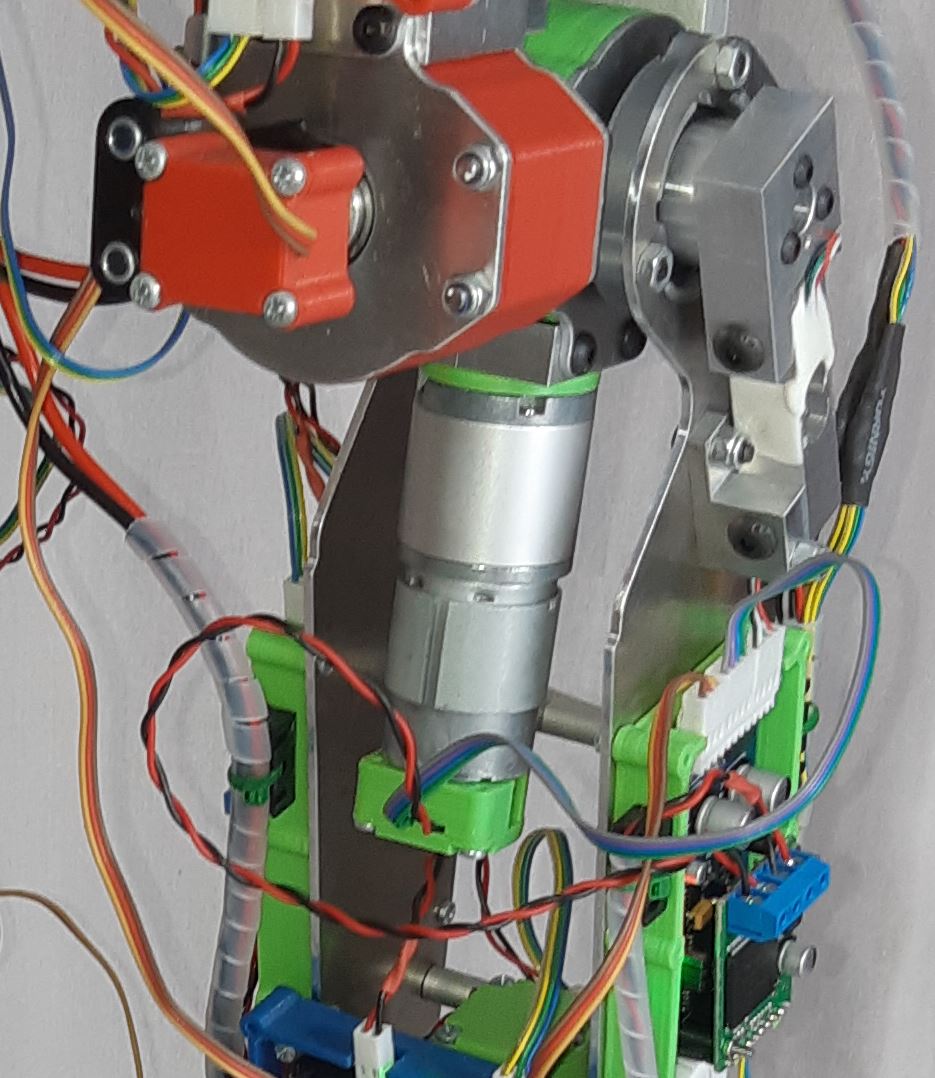
z1 and x2 have only Position Sensors when y3 has also a Torque Sensor. In order to measure y3 torque, the thigh assembly is mounted on the y3 output shaft with ball bearings (Purple) in order to rotate freely around it.

Then load cells supports are screwed, one on actuator shaft and the other on the thigh plate. Both supports are linked by the Load Cell with M5 screws.

Please note on the photo below the Load Cell which is connected to the Joint Control Board along with the position sensors and the motor power supply.