Worm Gear Actuator Description
The shaft is turned from Aluminium alloy (7075) and carries a 40 teeth brass gear held by four M3 domed head screws. Two ball bearing are mounted on the shaft. A 3D printed spacer is inserted between the gear and the smaller ball bearing in order to set the shaft axially.
The shaft + ball bearings assembly is inserted into two 3D printed half shells.
Two CNC machined 2mm aluminium alloy (7075) plates on each side of the shells close the actuator assembly. These plates are in contact with the ball bearings outer rings. They also carry the worm assembly and support the loads generated during the robot motion. Additional holes are available to allow assembly with other robot components.
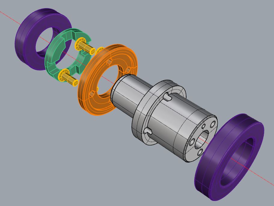
The worm shaft is made out of 4 mm steel. The steel worm is locked on the shaft with a 1.5 mm pin. The shaft is guided by 2 flanged ball bearing (purple) to accomodate radial load and 2 thrust bearings (salmon color) to accomodate axial load. Washers are inserted between radial and thrust bearings so that the axial load passes through the fixed outer rings of the radial ball bearings
One shaft end holds a steel slotted nut and the other end is threaded for a M4 nylstop nut.

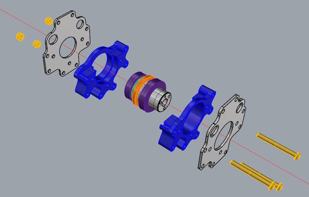
The worm shaft is encased into a aluminium alloy housing (7075). This housing holds a 3D printed flange to mount the motoreducer. A 3D printed cap is also fitted in order to protect the mechanism from dust and prevent grease from leaking. Both parts are glued with epoxy.
The housing has four M3 tapped holes that hold the bushings and cams. The bushings, positionned opposite to the motoreducer, are inserted into bores machined into the aluminium plates of the gear assembly. The cams are inserted into slotted holes in the aluminium plates and can be rotated in order to tune/minimise clearance between worm and gear.
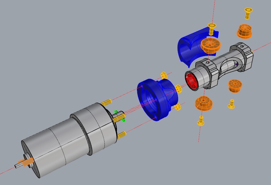
The motor has a 5:1 planetary gearset reducer. The reducer output shaft holds a 2 mm cross pin which drives the worm shaft slotted nut.
The overall gear reduction of the actuator is 200:1 (5 for the epicyclic reducer and 40 for the worm gear).
The whole actuator assembly looks like this:
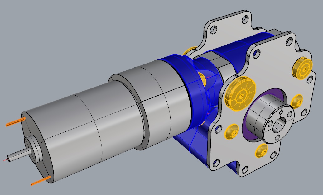
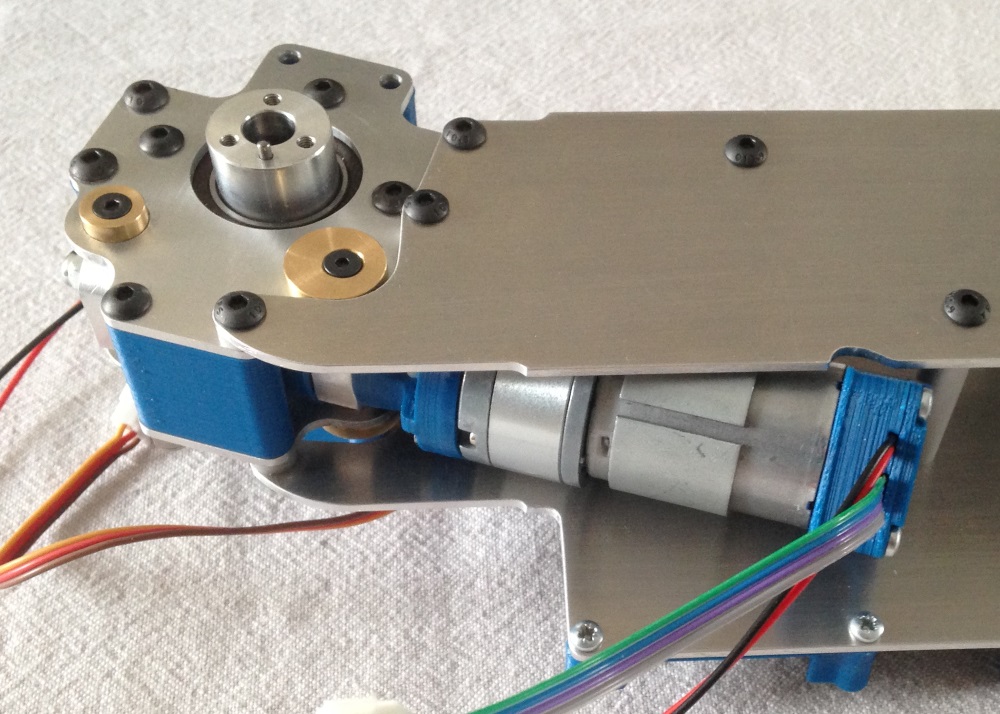
Picture of the Worm drive assembly. The worm gear is greased. The cams are not yet mounted. Note the encoder case on the motor (described in Position Sensors Section).

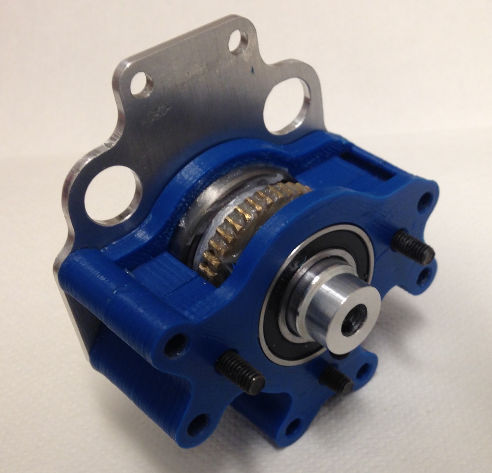
The gear housing partially assembled. Note the slotted hole on the aluminium plate that helps setting the clearance between worm and gear with the cam.
The worm gear actuator fully assembled and mounted on the pelvis plate. Note the bushing and cam machined from brass.