

Joints / Articulations arrangement
I wanted to have a Robot able to walk in straight line but also to steer and possibly later to progress on uneven terrain. So I decided to have 6 Joints / degrees of freedom per leg :
- 3 joints on the hip
- 1 joint on the knee
- 2 degrees on the ankle
The leg joints are connected like this :
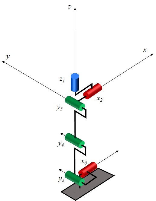
The first joint, z1, is only used when steering the robot. I used a worm gear actuator for this joint as its load is quite small and not depending on the robot weight.
Joint x2 is used to swing the leg sideways. This joint is the most heavily loaded as it carries the cantilevered weight of the opposite lifted leg when walking.
Joint y3 is used to swing the leg forward and rearward
z1, x2 and y3 cross each other on a single point.
Joint y4 is the knee articulation.
Joints x2, y3 and y4 use bevel gear actuators and joint x2 uses a bigger size electric motor.
Joints y5 and x6 are the ankle articulations. It is difficult to design a light ankle with bevel gear or worm gear actuators, so I chose to use 2 linear actuators driving both axis at the same time :
- y5 articulation is achieved when both linear actuator work in parallel (i.e. when both actuators retract or extend together at the same speed).
- x6 articulation is achieved when linear actuators work in opposition (i.e. when one actuator retracts while the other extends).
The ankle articulation is a cardan joint allowing rotation around y5 and x6 axis only.
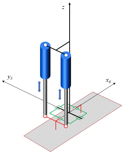
A general CAD view of the Robot :

The position sensors (potentiometers) of y5 and x6 are respectively in the green and red boxes. The light cyan blocks connected o the linear actuators are the load cells that measure the ankle torques, used to control balance of the robot while walking.
Actuators
Sensors
Leg Design
Electronics
- Joints Control Boards
- Interface Boards
Control / Softwares
- Joints Control
- Robot Control
